PyCom LoPy
Introduction
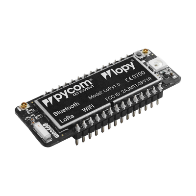
The LoPy is a microcontroller developed by PyCom that has LoRa, WiFi and Bluetooth modules on it, perfectly suited for the Internet of Things. It uses the latest Espressif chipset that runs MicroPython.

It can act as both a LoRa Nano Gateway and a multi-bearer (LoRa, WiFi and BLE) development platform suitable for all LoRa networks around the globe. It is programmable with MicroPython and the Pymakr plugin IDE for fast IoT application development, easy programming in-field and extra resilience with network failover. The best blend of speed to deployment and access to new LPWAN networks rolling out across Europe, USA, Africa and India. The LoPy is CE, FCC approved and is LoRaWAN certified.
Features
Overview:
- Powerful CPU, BLE and state of the art WiFi radio with upto 1 km WiFi Range
- Can also double up as Nano LoRa gateway
- MicroPython enabled
- Fits in a standard breadboard (with headers)
- Ultra-low power usage
- Semtech LoRa transceiver SX1272
- Class A and C operation
Processing & Memory:
- Espressif ESP32 chipset
- Dual processor + WiFi radio System on chip
- Network processor handles the WiFi connectivity and the IPv6 stack
- Main processor is entirely free to run the user application
- An extra ULP-coprocessor that can monitor GPIOs, the ADC channels and control most of the internal peripherals during deep-sleep mode while only consuming 25uA
- RAM: 512KB
- External flash: 4MB
- Hardware floating point acceleration
- Python multi-threading
Frequencies & Range:
- 868 MHz (Europe) at +14dBm maximum
- 915 MHz (North and South America, Australia and New Zealand) at +20dBm maximum
- Node range: Up to 40km
- Nano-gateway: Up to 22km
- Nano-gateway capacity: Up to 100 nodes
Interfaces:
- 2 x UART, 2 x SPI, I2C, I2S, micro SD card
- Analog channels: 8×12 bit ADCs
- Timers: 4×16 bit with PWM and input capture
- DMA on all peripherals
- GPIO: Up to 24
Power:
- Input: 3.3V – 5.5V
- 3v3 output capable of sourcing up to 400mA
- WiFi: 12mA in active mode, 5uA in standby
- LoRa: 15mA in active mode, 1-uA in standby
Getting Started
Connecting to the Device
- Open terminal
- Execute this command
ls -lhat /dev/tty* - You should see something like
/dev/tty.usbserial-DQ00D7YX - Issue the following command to connect to the REPL
Device EUI
To get the DevEUI, issue the following command on the REPL
It will print to console the deveui of the device. Now use this deveui to provision it in ThingPark. The information on how to provision a device can be found on this link Device Provisioning using ThingPark Device Manager.
AS923 Firmware
If your LoPy firmware version is older than v1.16.0-b1, which was released on February 15, 2018, then it will not correctly support the Spark LoRaWAN AS923 network that we operate. Below are instructions for updating the device’s firmware.
Update the LoPy Firmware
The latest version of the PyCom files can be fetched from the following links:
- PyCom downloads page
- MacOS firmware update utility
- Windows firmware update utility
- Linux firmware update tool
Before running the Linux updater you might need to run:
in the command line.
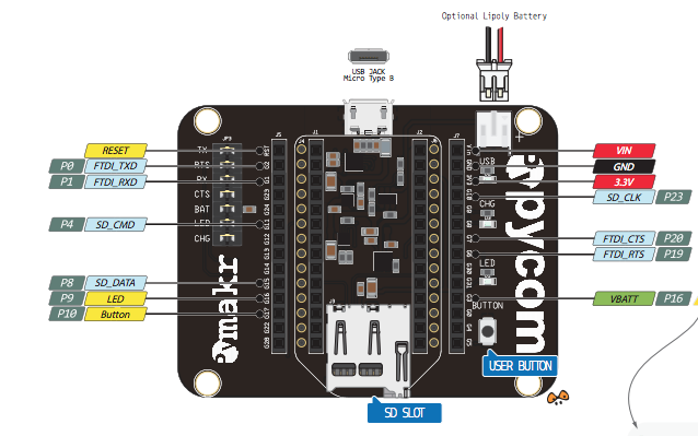
To update the firmware, this guide assumes that you have a PyCom PyBoard that you can use to power the device, and communicate with it. The pinout for the PyBoard is given in the following figure:

Set Device to Update Firmware Mode
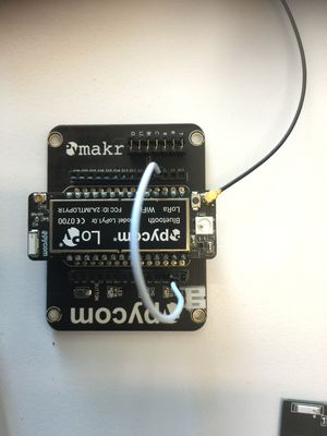
Remove the device from the power source and connect a wire between the pins GND and G23.

Update Firmware
Now follow the update steps. You will need to launch a terminal and issue to following commands.
- Create update folder under home directory and copy the firmware from Downloads folder:
- Extract the updater:
- Perform the update: